


Featured articles
More from the category
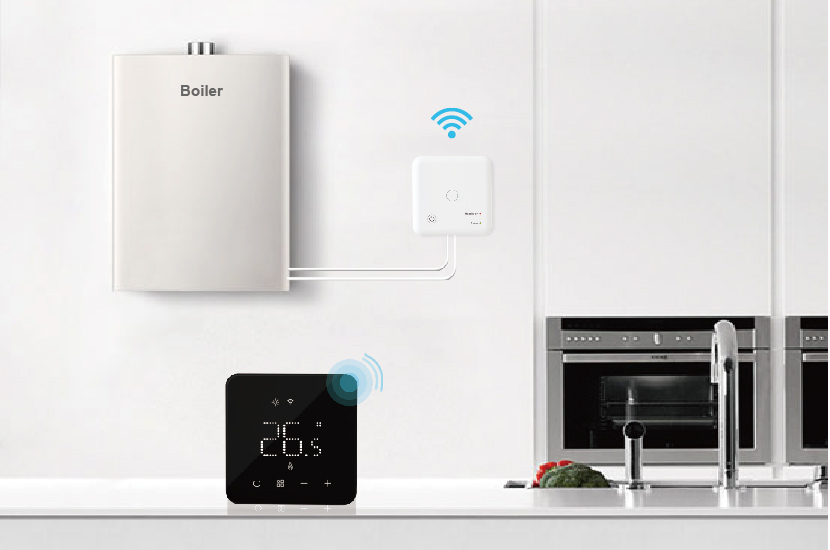

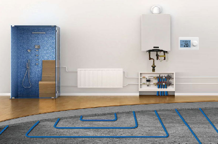
In industrial production and home heating, the stable operation of the boiler is crucial. As the core component for controlling the temperature of the boiler, the correct wiring of the boiler thermostat is the key to ensuring the normal operation of the boiler. This article will introduce the wiring method, precautions and common problem solving of the boiler thermostat in detail to help readers master this important skill.
Preparation before wiring
Understand the type and specification of the thermostat
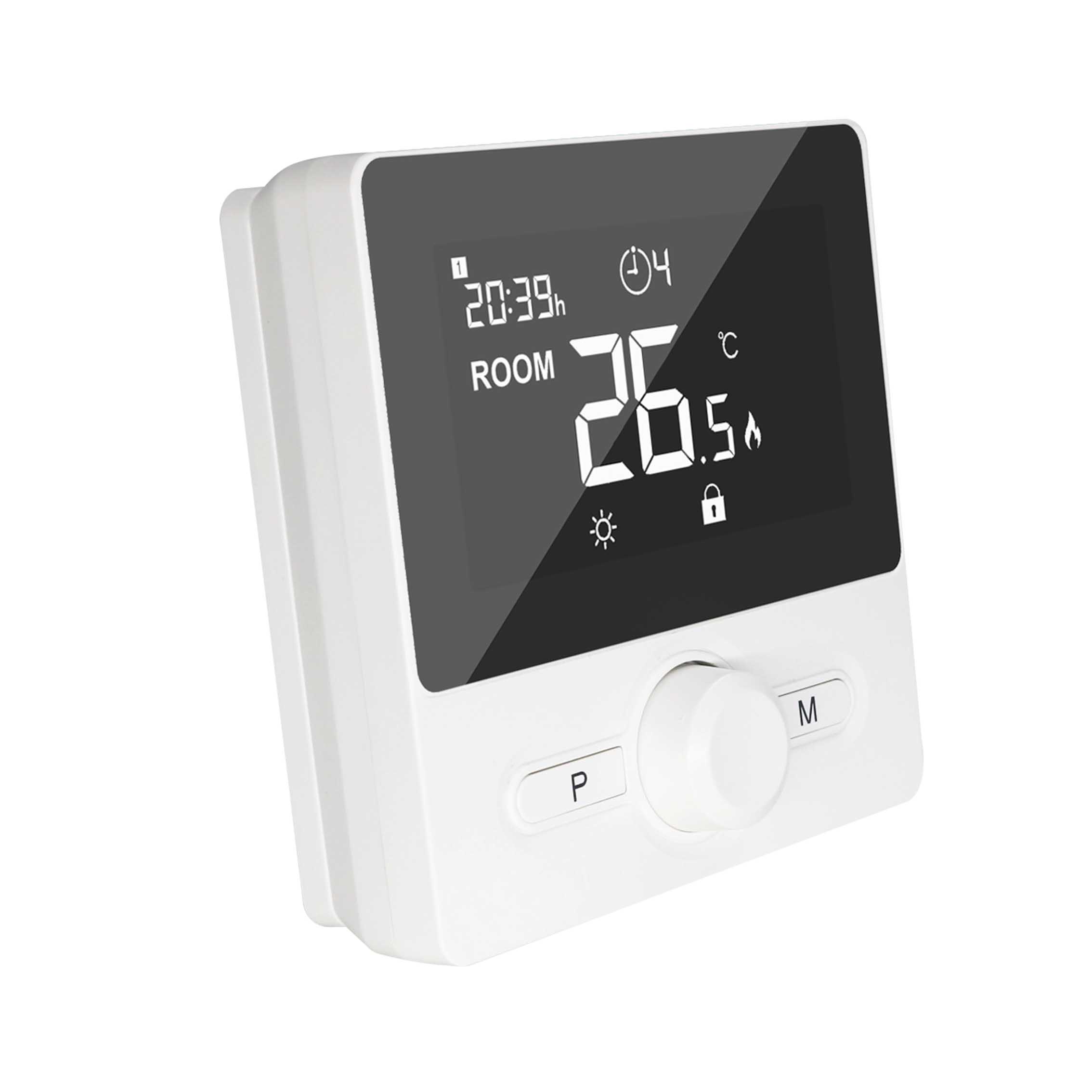
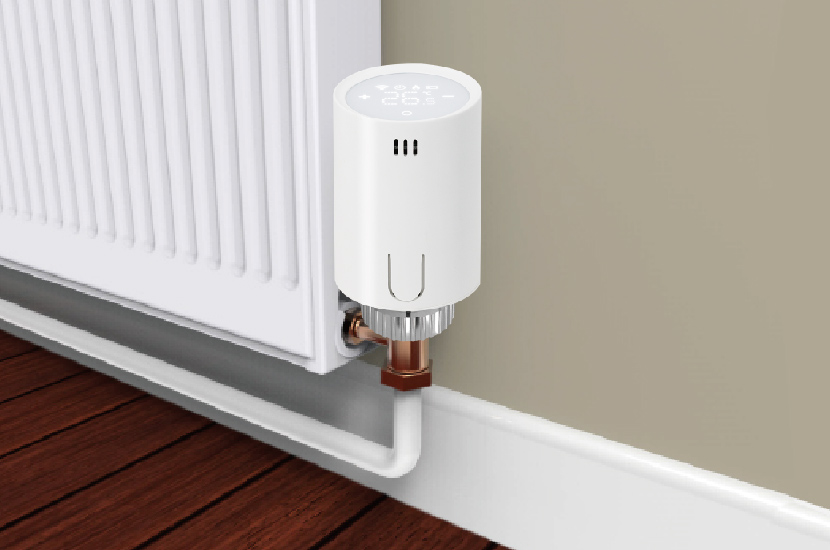
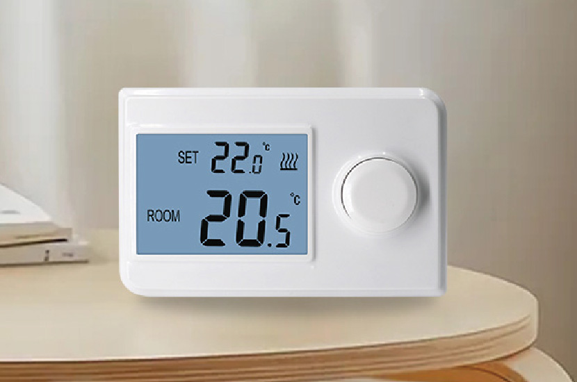
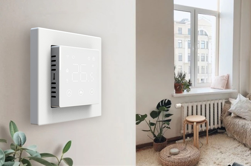
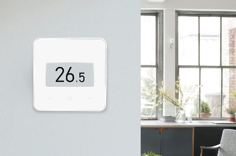
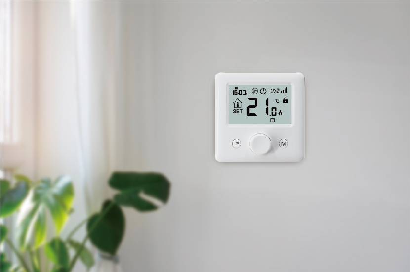
First, it is necessary to clarify the type of boiler thermostat used. Common ones are mechanical thermostats and electronic thermostats. Mechanical thermostats mainly sense temperature through mechanical structures such as bimetallic strips; electronic thermostats use sensors and electronic circuits to measure and control temperature, with higher accuracy and richer functions.
Prepare tools and materials
The tools required include screwdrivers (cross, flat), wire strippers, multimeters, electrical tape, etc. In terms of materials, it is necessary to prepare suitable wires, and the cross-sectional area of the wires should be selected according to the rated current of the thermostat and boiler.
Power off and check the equipment
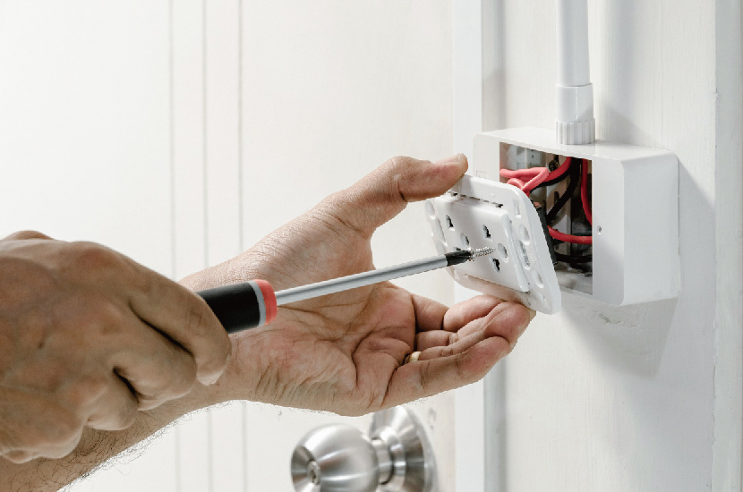
Before wiring, be sure to disconnect the main power supply of the boiler system to ensure safe operation. At the same time, check whether the wiring terminals of the boiler thermostat and the boiler body are intact, whether there is rust, looseness, etc. If there is a problem, clean or repair it first.
Detailed explanation of wiring steps
Determine the function of the wiring terminal
The terminal markings and functions of different types of boiler thermostats may vary slightly, but usually include the following types of terminals:
Power terminal: used to connect to an external power supply, generally marked as “AC220V”, “L” (live wire), “N” (neutral wire), etc. For thermostats with three-phase power supply, there may be “R”, “S”, “T” and other markings to indicate the three-phase live wire.
Temperature sensor terminal: used to connect temperature sensors, such as thermocouples (marked as “TC+”, “TC-“), thermal resistors (marked as “RTD1”, “RTD2”, “RTD3”), etc. The wiring method of the sensor must be strictly in accordance with the thermostat manual to avoid reverse connection or short circuit.
Output control terminal: used to control the heating equipment of the boiler (such as electric heating tubes, burners, etc.), usually divided into relay output (marked as “COM”, “NO”, “NC”), solid-state relay output (“SSR+”, “SSR-“), etc., select the corresponding output terminal according to the type of control object.
Auxiliary function terminal: Some thermostats have auxiliary terminals such as alarm output, remote control input, communication interface (such as RS485), which can be wired according to actual needs.
Specific wiring operation
Take the common single-phase 220V power supply, equipped with thermocouple sensor and relay output electronic thermostat as an example, the wiring steps are as follows:
Power supply wiring: Connect the live wire (L) of the power supply to the “AC220V L” terminal of the thermostat, and the neutral wire (N) to the “AC220V N” terminal. When wiring, use wire strippers to strip about 10mm of insulation at the end of the wire, insert it into the terminal hole, and tighten the terminal screw with a screwdriver to ensure good contact.
Sensor wiring: Connect the positive pole of the thermocouple (usually the red wire) to the “TC+” terminal of the thermostat, and the negative pole (usually the black wire) to the “TC-” terminal. Note that the type of thermocouple (such as K type, J type, etc.) must be consistent with the sensor type set in the thermostat, otherwise it will cause inaccurate temperature measurement.
Output control wiring: Assuming that the control object is a relay of an electric heating boiler, connect one end of the relay coil to the “COM” terminal of the thermostat, and the other end to the neutral wire (N) of the power supply. The “NO” terminal (normally open contact) of the thermostat is connected to the live wire (L) of the power supply. When the temperature is lower than the set value, the thermostat contact closes, the relay coil is energized, and the heating equipment starts working; when the temperature reaches the set value, the contact opens and the heating stops. If you need to control equipment such as burners, the wiring principle is similar, but you need to pay attention to whether the working voltage and current of the equipment match the output capacity of the thermostat.
Auxiliary function wiring (if necessary): If you need to connect the alarm output, when the temperature exceeds the set upper or lower limit, the alarm contact will act. The alarm terminal (such as “AL1+”, “AL1-“) can be connected to the alarm indicator or buzzer. For remote control input, the external control signal (such as the switch signal) can be connected to the corresponding input terminal to realize remote start and stop or temperature setting functions.
Precautions
Safety first
Always perform wiring operations in the power-off state to avoid the risk of electric shock. After the wiring is completed, check whether all wiring is firm to prevent looseness from causing short circuits or poor contact.
Strictly follow the instructions
The wiring methods of boiler thermostats of different brands and models may be different. Be sure to read the installation instructions of the thermostat carefully and operate according to the specified terminal markings and wiring diagrams. If you have any questions about the wiring, you can contact the manufacturer’s technical support personnel for consultation.
Grounding treatment
For thermostats and boiler equipment with metal shells, reliable grounding treatment should be carried out, and the grounding wire should be connected to a dedicated grounding terminal. The grounding resistance should meet relevant standards to prevent safety accidents such as leakage and lightning strikes.
Correct wiring is the basis for the normal operation of the boiler thermostat and is related to the safe, stable and efficient operation of the boiler system. During the wiring process, you need to make full preparations, strictly follow the instructions, pay attention to safety matters, and promptly check and solve common problems. Through the introduction of this article, I hope that readers can master the wiring method of the boiler thermostat and provide guarantee for the reliable operation of the boiler system. If you encounter complex problems in actual operation, it is recommended to seek the help of professional technicians to ensure the accuracy and safety of the wiring work.