In underfloor heating, HVAC, or central air conditioning systems, thermostats are the key components for temperature regulation and comfort control, while their wiring serves as the vital link between “control signals” and “execution.” Poor contact, incorrect connections, or damaged wiring can lead to issues like abnormal temperature readings, device failure to start, or uncontrolled heating/cooling. These problems may stem from improper wiring during installation, damage to cables during renovation, or aging and loosening from prolonged use. Without timely inspection and repair, such issues not only compromise comfort but may also increase energy consumption and even pose safety hazards.
Preparatory Work Before Inspecting Thermostat Circuits
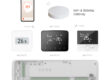
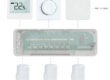
Proper preparation before inspecting electrical circuits can prevent operational errors and safety hazards. First, identify the thermostat type—whether wired or wireless with a wired base, as wiring methods differ slightly between types. Next, confirm the system type controlled by the thermostat, such as underfloor heating, water heating, electric underfloor heating, or fan coil systems, as each requires distinct wiring specifications. Prior to inspection, ensure all power sources are disconnected, including the thermostat’s power supply and connected devices. This step safeguards both equipment and personal safety. Prepare basic tools like screwdrivers, flashlights, and circuit labels to streamline the process. Additionally, bring original wiring diagrams or installation manuals for cross-checking.
Inspection of Thermostat Appearance and Terminal Blocks
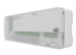
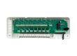
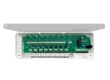
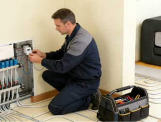
When inspecting thermostat wiring, the initial step typically involves examining the exterior and terminal connections. After opening the thermostat panel, check if the wiring is neatly arranged and securely fastened. Loose, disconnected, or improperly crimped wires are common causes of signal instability. For terminal connections, pay attention to the following: whether wires are properly inserted and screws are tightened; if multiple wires are crimped onto a single terminal; if insulation is damaged or copper wires are excessively exposed. Additionally, look for visible burn marks, discoloration, or unusual odors, which may indicate overloading or poor contact. If such issues are detected, immediately stop using the device and perform further troubleshooting.
line inspection
In addition to inspecting the internal wiring of the thermostat unit, the overall routing of the electrical circuits must be examined. Thermostat wiring typically extends from interior walls or cable trays to the wiring center, control box, or actuating devices. Along the circuit path, check for the following: potential compression from nails, screws, or furniture; damage from cutting, abrasion, or breakage during renovation; or exposed wiring in damp or high-temperature environments due to damaged conduits. Special attention should be paid to junctions and corners where wiring passes through walls or floors, as these areas are more prone to hidden damage. Ensuring the wiring remains intact and free from visible stress is essential for maintaining stable signal transmission in thermostats.
Basic confirmation of power supply and signal line
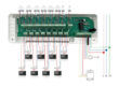
Thermostat circuits typically consist of power supply lines and signal control lines. During inspection, it is essential to clearly distinguish the functions of these different circuits to avoid confusion. The power supply line primarily provides electricity to the thermostat, while the signal line transmits control commands to actuators, boilers, or the wiring center. Under the premise of ensuring electrical safety, verify that circuit labels are clearly marked and connections adhere to the original design. For multi-zone systems, confirm that each thermostat is properly connected to its designated control circuit to prevent misconnections that could cause operational chaos. If a thermostat displays abnormal readings or fails to respond to settings, this is often due to issues with the power supply or signal line connections.
Common Line Problems and Troubleshooting Approaches
During actual inspections, certain issues frequently occur. For instance, loose wiring may cause the thermostat to malfunction intermittently, while reversed wiring could prevent the device from starting. Additionally, unmarked wires often lead to incorrect connections during maintenance. To address these problems, technicians should systematically verify and resolve each issue rather than making extensive wiring modifications all at once. During inspections, it’s advisable to focus on adjusting a single problematic point at a time, then observe the system’s response to pinpoint the root cause. Furthermore, avoid altering wiring connections arbitrarily to prevent triggering new faults.
Thermostat circuit inspection isn’t technically demanding, but it requires patience, meticulousness, and standardized procedures. By performing these steps—preemptively disconnecting power, inspecting appearance and terminal connections, verifying wiring integrity, and testing power/signal line functionality—most common issues can be promptly identified and resolved. Proper circuit condition forms the foundation for stable thermostat operation and efficient temperature control system performance. During routine use, regularly checking thermostat responsiveness and display accuracy helps detect potential wiring issues early. When obvious damage or unresolved problems are found, seeking professional assistance promptly ensures system safety and long-term stability. Systematic, scientific circuit inspections effectively reduce malfunctions while enhancing overall heating or cooling experience.