In residential heating and hot water supply systems, the boiler thermostat is a core control device, and its connection quality directly affects system efficiency and safety. Whether it’s a traditional mechanical thermostat or an intelligent electronic device, correct wiring procedures and debugging methods are crucial to ensuring stable operation. This article will systematically analyze the entire connection process of a boiler thermostat, from basic wiring principles to practical installation examples.

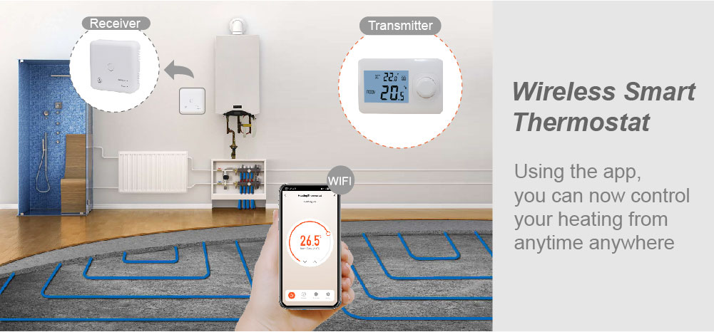
The core function of a boiler thermostat is to monitor the ambient or medium temperature in real time through a temperature sensor and control the start and stop of the heating equipment by comparing it with a set value. Its working principle can be simplified to three stages: “sensing-judgment-execution”: the sensor collects the temperature signal, the microprocessor analyzes the data, and the relay or solenoid valve executes the switching action. In this process, the wiring directly determines the stability of signal transmission and the safety of the equipment. Taking a common wall-hung boiler system as an example, the thermostat needs to be connected to the power cord, control cord, and sensor cord simultaneously. Incorrect wiring can lead to equipment damage or safety hazards.
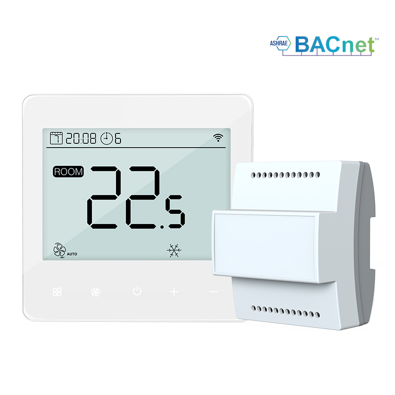
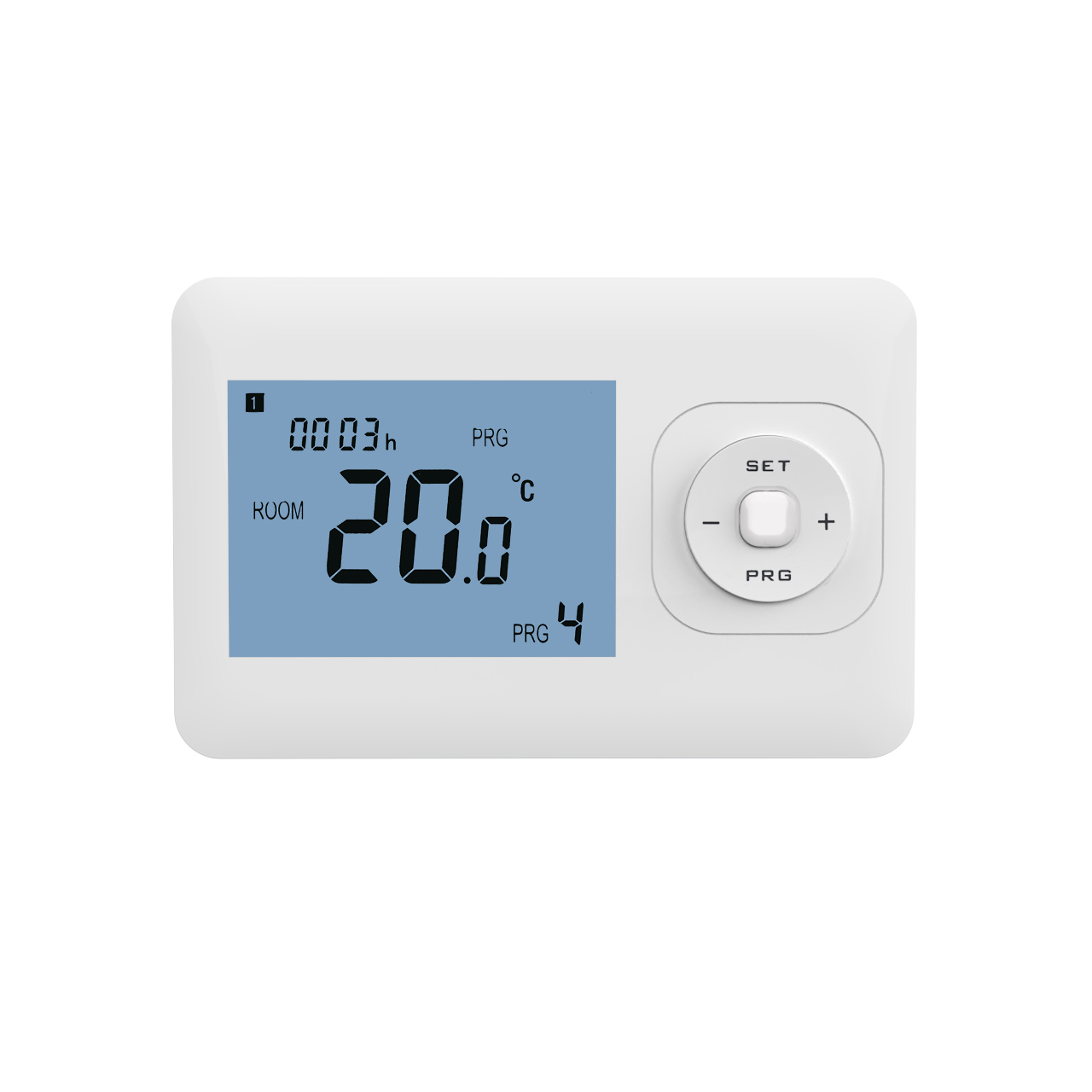
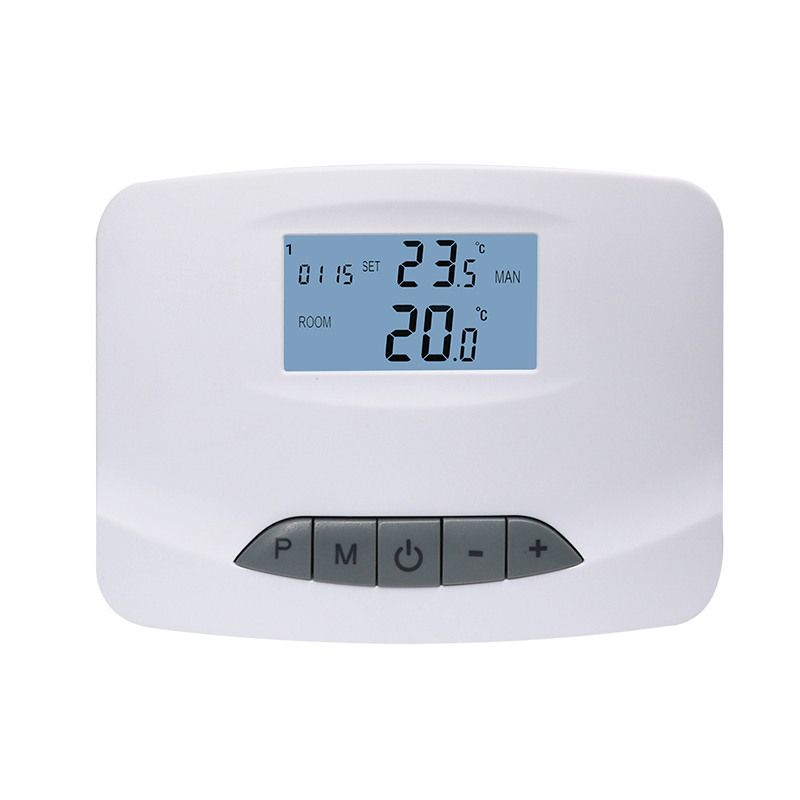
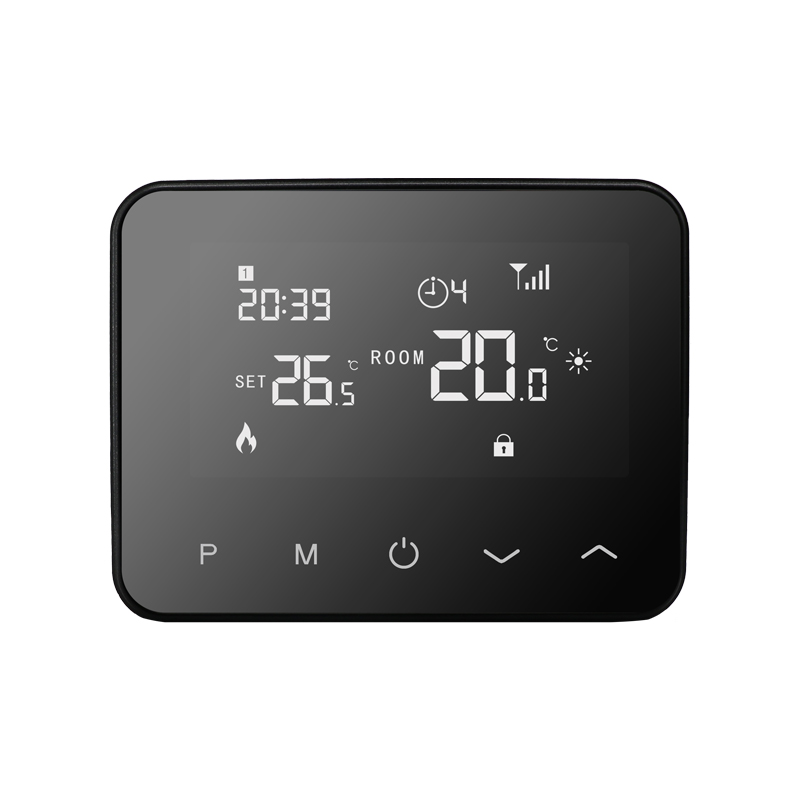
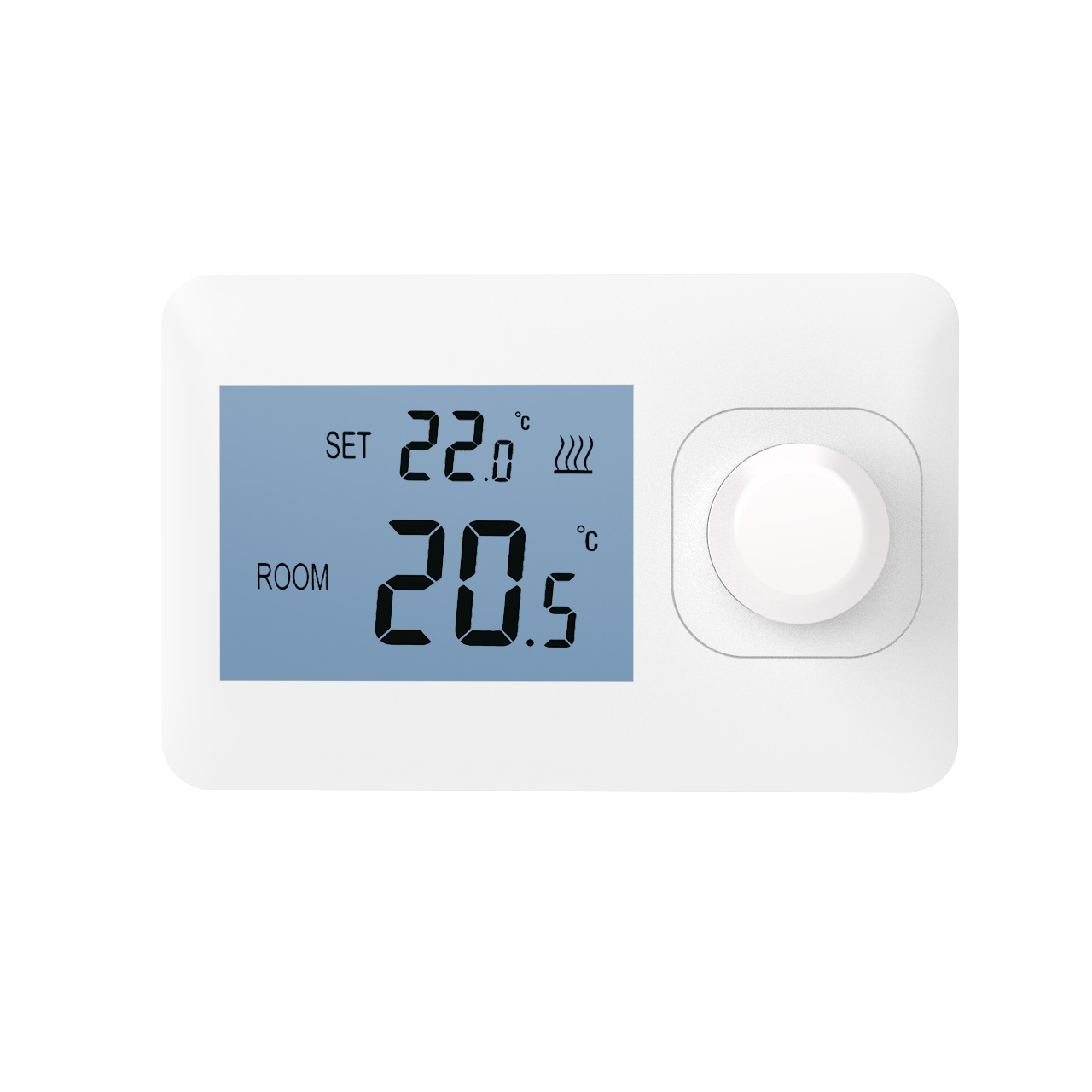
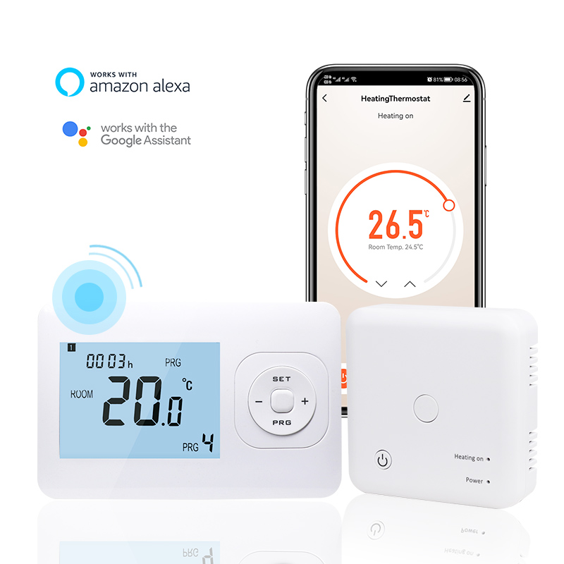
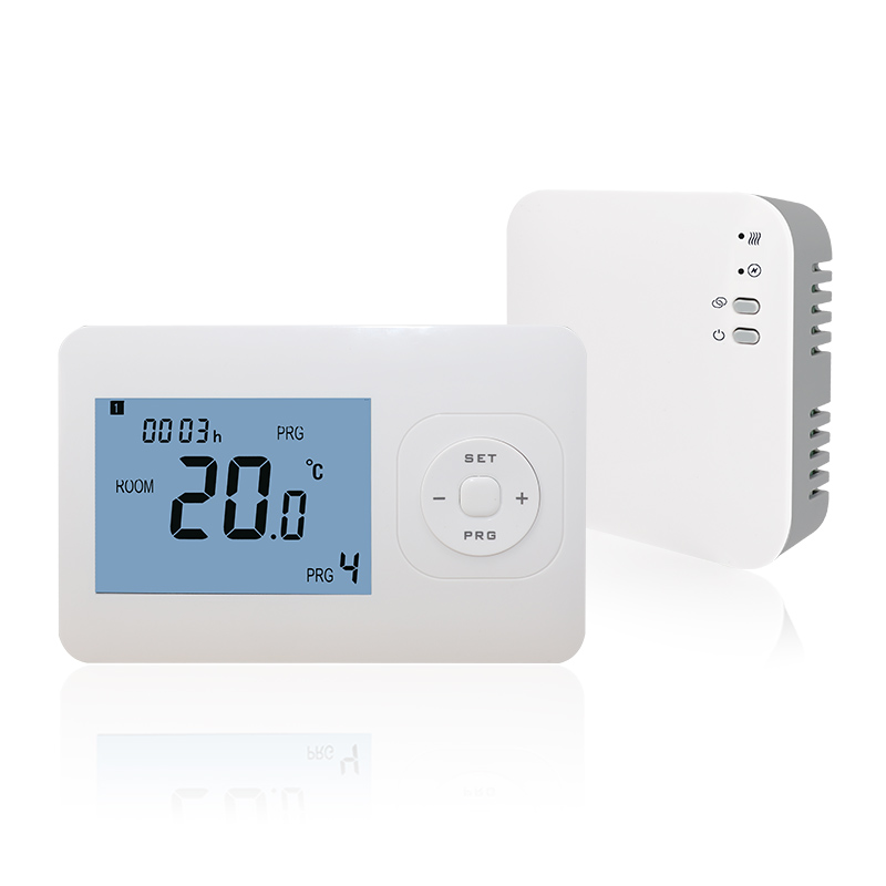
Basic wiring procedures must strictly adhere to the safety principle of “disconnect power before operation.” The first step is to connect the power cord. Ensure the power supply voltage matches the equipment markings; typically, 220V AC is used. Connect the live wire (L) to the thermostat’s power terminal and the neutral wire (N) to the common terminal. The second step is to connect the control wires. Match the boiler control interface to the thermostat’s output. For example, connect the COM terminal (common terminal) and the NO terminal (normally open terminal) in series to the boiler heating circuit, forming a closed-loop control system from thermostat to boiler. The third step is to connect the sensor wires. Select a thermocouple or resistance temperature detector (RTD) sensor based on the equipment type, ensuring the probe is inserted to the correct depth in the pipe or immersed in liquid to avoid measurement errors. For example, a certain brand of electronic thermostat clearly labels its terminals with L, N, COM, NO, and NC. Users simply need to connect the corresponding wires according to the diagram to complete the basic connection.
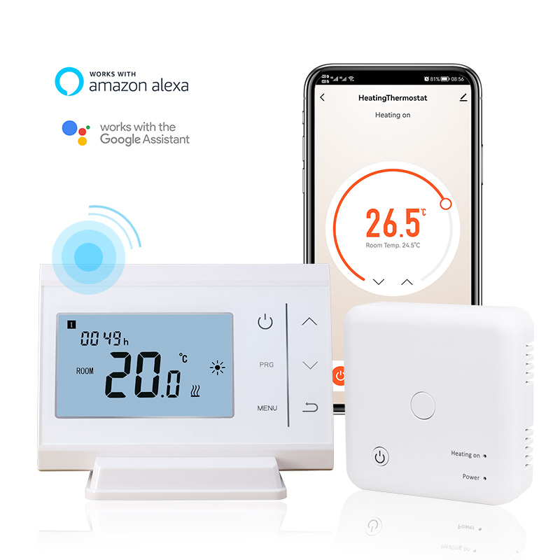
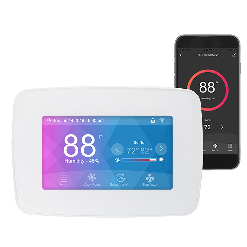
Advanced debugging requires optimizing parameters based on equipment characteristics. For programmable thermostats, a temperature hysteresis value needs to be set to avoid frequent start-stop cycles. For example, if the target temperature is set to 22℃, setting the hysteresis to 2℃ will start heating when the temperature drops to 20℃ and stop when it rises to 22℃. Smart thermostats also require network pairing. Remote control is achieved by scanning the device’s QR code or entering the serial number via a mobile app. Some models support voice assistant integration, further simplifying the operation process. Special attention must be paid to sensor calibration during commissioning. For example, the probe should be placed in an ice-water mixture to verify the 0℃ reading, or placed in boiling water to verify the 100℃ reading. If the error exceeds ±1℃, the device parameters need to be adjusted or the sensor replaced.
In actual installation cases, the thermostat connection of the wall-hung boiler system needs to balance functionality and aesthetics. Taking a three-bedroom, two-living-room apartment as an example, a main thermostat can be installed in the living room, connected to the boiler control panel via a signal cable. Simultaneously, individual room thermostats can be installed in the bedrooms, controlling the water flow in each area via electric valves. This distributed layout achieves zoned temperature control while avoiding the problem of insufficient coverage from a single thermostat. During installation, cable trays should be reserved to conceal the wiring. The thermostat height is recommended to be around 1.4 meters, avoiding interference sources such as doors, windows, and radiators. A user reported that by strategically arranging thermostats, winter heating energy consumption was reduced by 15%, while indoor temperature fluctuations decreased from ±3℃ to ±0.5℃, significantly improving comfort.
Connecting a boiler thermostat is a process that combines technical skill and experience. From basic wiring to parameter adjustment, every step must strictly adhere to the equipment manual and electrical safety regulations. With the development of smart home technology, modern thermostats possess advanced functions such as self-learning and energy consumption monitoring, but their core wiring logic remains based on traditional temperature control principles. Mastering the correct connection methods not only extends the equipment’s lifespan but also achieves energy conservation and emission reduction goals through precise temperature control. Whether DIY installation or professional construction, understanding the equipment’s working principles and wiring points is fundamental to ensuring stable system operation, and this is a crucial step in improving the home heating experience.