Fan coil unit (FCU) thermostats are critical control terminals in HVAC systems, responsible for regulating indoor temperature and fan operation. Proper wiring ensures not only the correct functioning of the thermostat but also the stable operation of the entire fan coil system. For engineers and maintenance personnel, mastering the wiring method is essential. This article provides a detailed analysis of FCU thermostat wiring principles, common interfaces, step-by-step wiring procedures, and precautions.
Overview of Wiring Principles
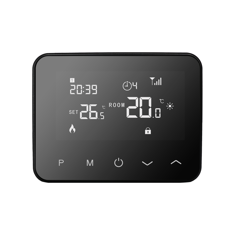
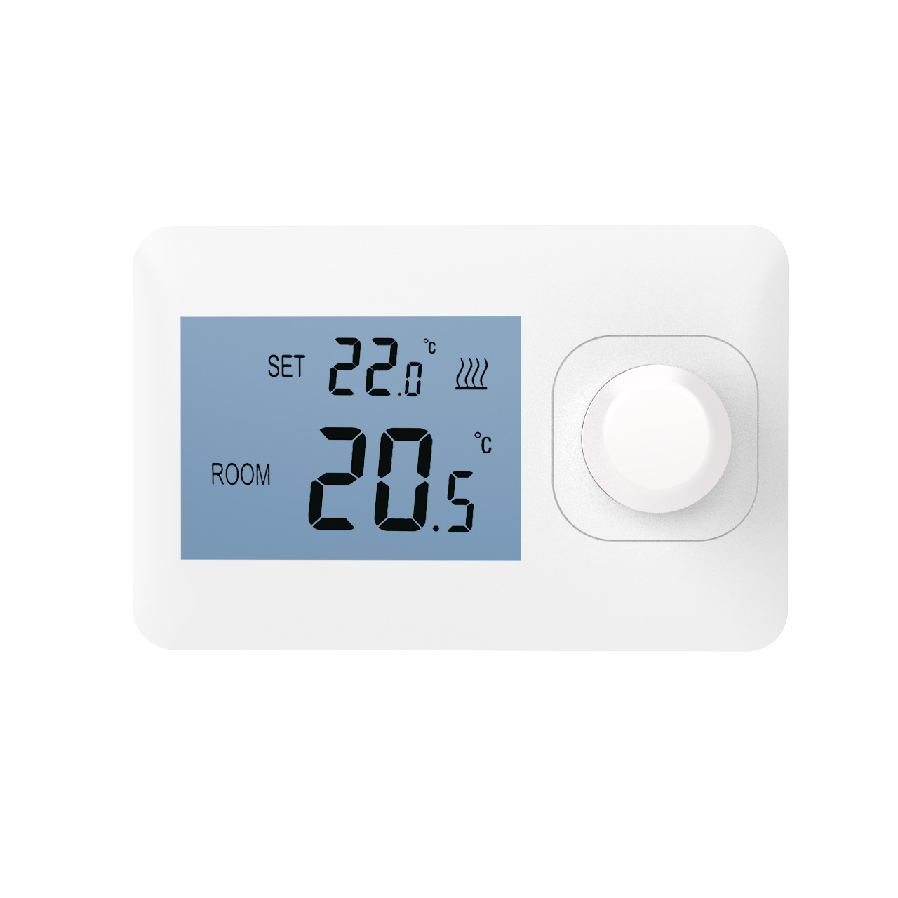
FCU thermostats primarily control fan operation levels and the opening/closing of heating or cooling valves. The main types of wiring signals include:
Power lines: Supply electricity to the thermostat, usually AC 24V or DC 12–24V.
Temperature control signal lines: Connect to heating/cooling valves or proportional valves to regulate water flow.
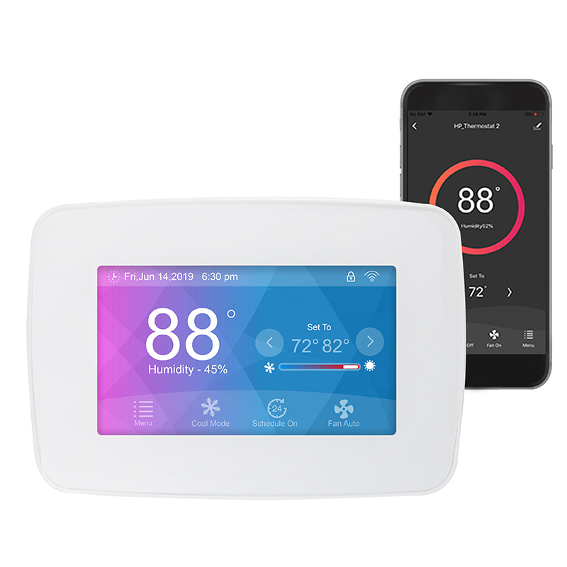
Fan control lines: Adjust fan speed or on/off status, including multi-speed switches or 0–10 V signal control.
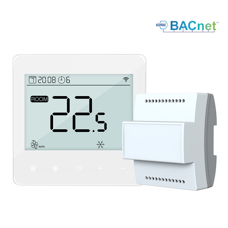
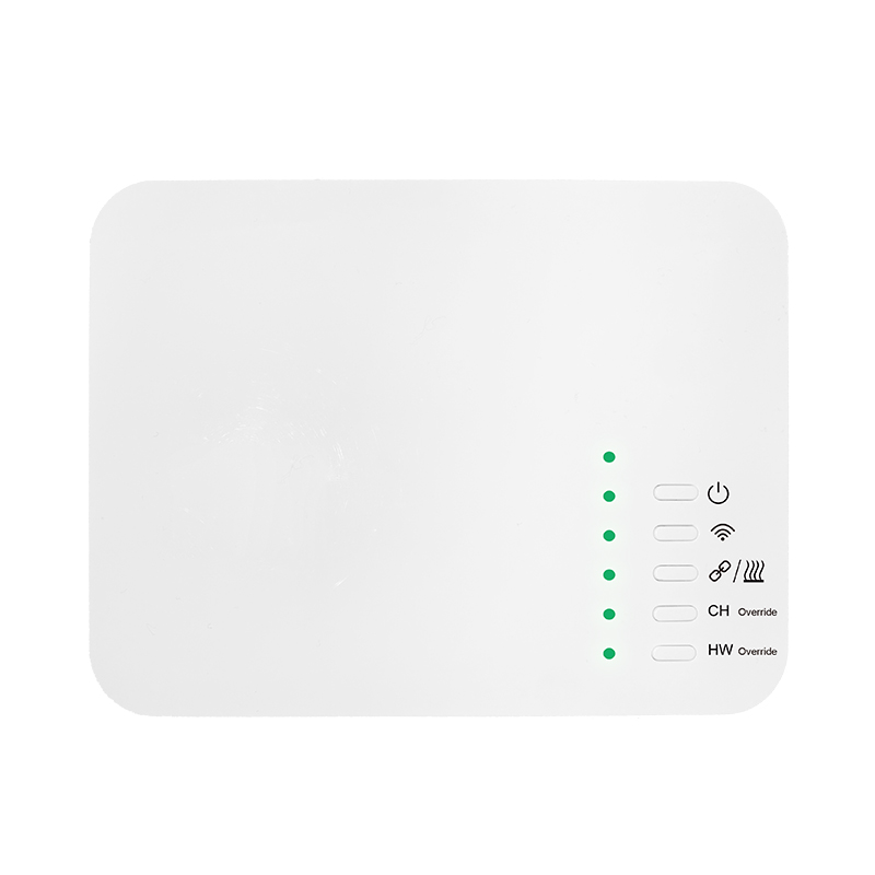
Communication lines (optional): In BMS systems, thermostats may communicate with the central system via Modbus or BACnet for centralized control and data acquisition.
Understanding the function of each line type is the foundation for correct wiring and helps avoid equipment damage.
Common Interface Types
Market-available FCU thermostats typically use:
Terminal block interfaces: Direct connection for power, valves, and fan control, common in small or traditional thermostats.
Plug-in interfaces: Easier maintenance and replacement, suitable for modular designs.
Communication interfaces: For BMS integration, usually RS-485 or RJ45 supporting Modbus or BACnet protocols.
Selecting the appropriate interface and wiring method improves installation efficiency and ensures stable signal transmission.
Step-by-Step Wiring Procedure
Power off
Always cut off power to the thermostat and fan coil system before wiring to ensure safety.
Identify terminal labels
Terminals are usually labeled for power (L/N), valve (CH/HC/Valve), fan (FAN/High/Medium/Low), and communication. Accurate identification prevents wiring errors.
Connect the power supply
Connect power lines to the corresponding terminals, ensuring correct polarity and matching the rated voltage of the thermostat.
Wire valves and fan
Connect cooling/heating valve lines, proportional valve lines, and fan speed lines according to the labels. For multi-speed fans, connect lines to High/Medium/Low terminals. For 0–10 V fan control, confirm signal and common lines are correctly connected.
Communication wiring (optional)
For BMS integration, connect Modbus or BACnet lines to the designated terminals. Ensure shielded wires are properly grounded to reduce interference.
Check all connections
Confirm all wires are secure, terminals are tight, and no exposed conductors could cause shorts.
Power on and test
After powering the system, verify thermostat response for fan and valve operation. Ensure all speed settings and temperature control functions operate correctly before normal operation.
Wiring Precautions
Follow the thermostat manual and national electrical safety codes during wiring.
Terminal labeling may vary by brand or model—always confirm the wiring diagram before installation.
For high-power fans or valves, use relays or contactors to isolate the load; do not let the thermostat directly drive high loads.
In BMS systems, route communication lines away from strong electrical cables to minimize interference.
Conclusion
Proper wiring of fan coil unit thermostats directly affects HVAC system stability and indoor comfort. By accurately identifying terminals, correctly connecting power, fan, and valve lines, and adhering to safety and communication requirements, thermostats can operate reliably both in standalone and BMS-integrated modes. Mastering correct wiring methods improves installation efficiency and lays the foundation for long-term system maintenance and energy optimization.